Solar-Powered WIKE Bike Trailer Project

Hey everyone; very belated happy new year. One person who recently visited my YouTube channel asked for a specific wiring diagram on my solar paneled bicycle trailer. So here goes.

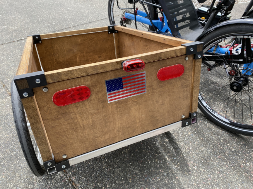
The kit was purchased from a Canadian company called WIKE. They are online and sell quality bicycle trailer kits. WIKE sells the main fiber glass fastener unit and stainless steel nuts and bolts. The purchaser supplies his/her own wood or aluminum tubing to build the main frame, and any additional fasteners they may need for the project. I purchased the “high-walled” kit.

WIKE bicycle trailer kit
WIKE high-walled trailer kit: finished project.

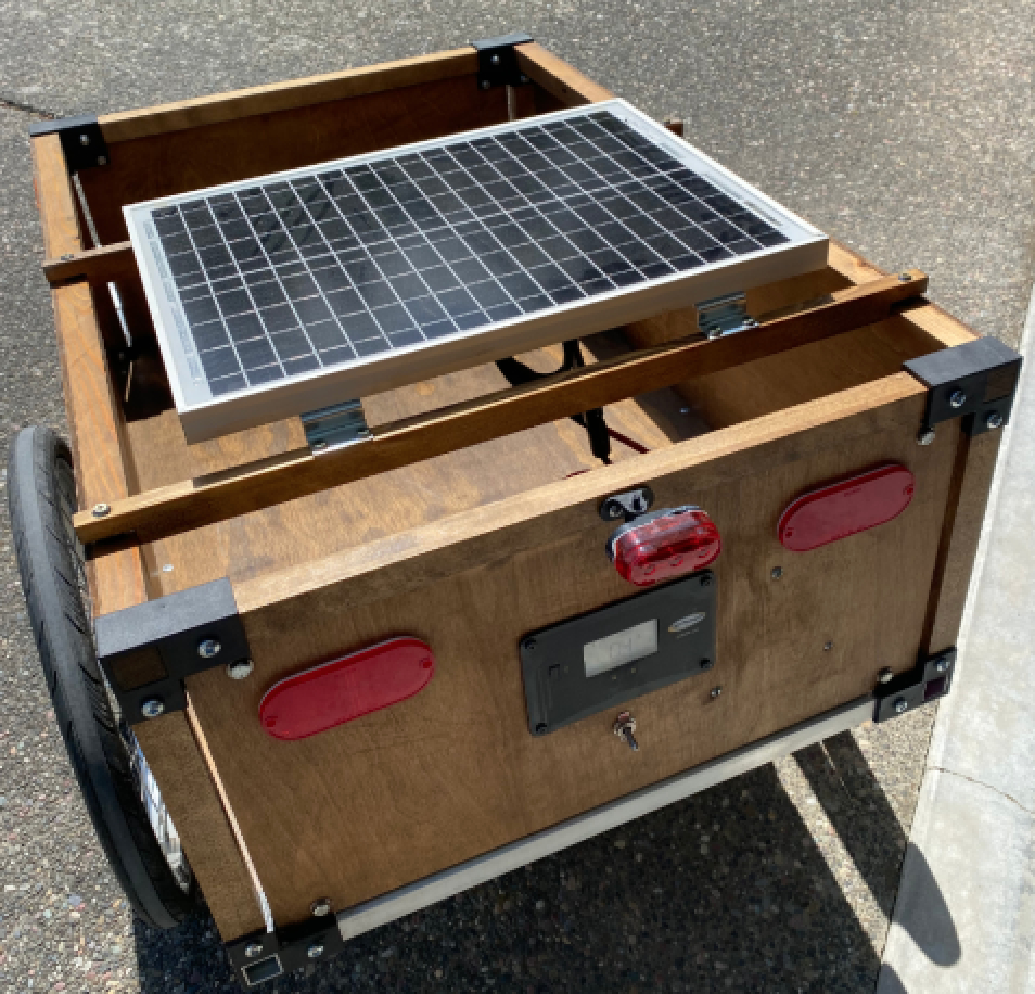
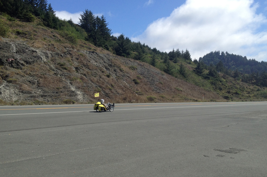
Above is the finished kit. It was big fun to build and is a breeze to tow. Here’s a link to the video where the build was explained.

On rough gravel it is a bit noisy, but quiets down on smooth pavement. Most of noise are the wheel axles rattling inside the mounting hardware. The black panel is the controller. The switch below the controller turns the inverter on or off. Two reflectors are peel-and-stick. The tail light is battery powered. Below is a diagram of how it is all wired up.

Solar panel wiring diagram

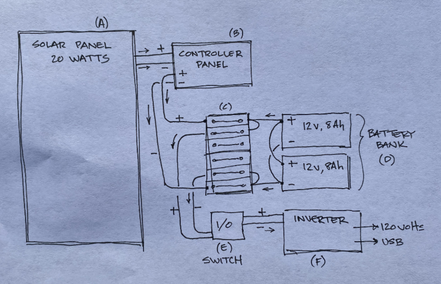
Forgive my drawing. I know I use to draw better than this. The components are not physically positioned in this exact representation and are not to scale. However, the wiring is correct. Small arrows indicate current flow.

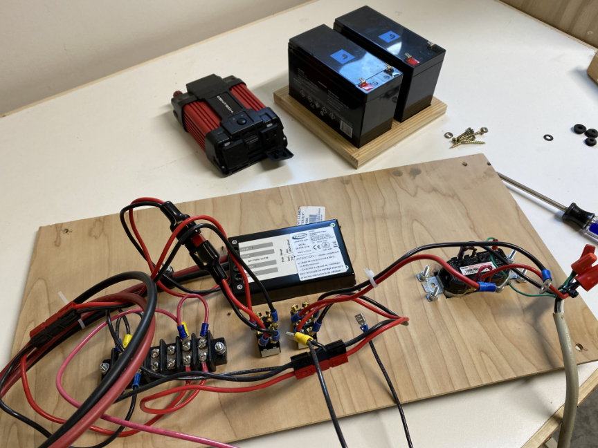
Components are linked together via the electrical distribution block (C). The batteries are wired in parallel (negative to negative/positive to positive.) One battery’s negative pole goes to the negative input side of the block; the positive pole of the other battery goes to the positive input side of the block. This gives me one battery of 12 volts and 16 amp hours. If you use more than one battery (i.e. three) make sure the positive pole from the battery on the end of the bank and the negative pole of the battery on the other end of the bank are connected to the controller. DO NOT connect only one battery’s poles into the electrical network, even though they are all connected in parallel. You must spread the load evenly across all batteries used.

The batteries are connected to the “input” side of the block (right side in the drawing). Two rows on the positive end and two rows on the negative end are wired together. From here the distribution block is connected directly to the controller panel (C). This is the only aspect of this setup I don’t like. The battery bank (D) is connected to the panel (C) 24/7, supplying power to the panels in order to display battery voltage, amp hours, current charging amperage, i.e. This will eventually drain the battery bank. In order to counter act this, I place the trailer in bright sunlight as often as possible. Otherwise, I disconnect the battery bank from the controller via an Anderson plug. I did have a switch installed here but decided it was not needed. (Thinking about re-installing this switch.)

From the other two live ports available on the “outgoing” side of the distribution block (C) wires go to a switch (E), then to the inverter (F). The inverter has two plugs for 120 volts output as well as USB outputs.

In conclusion, I don’t think this is the most efficient way to store/move electrical power. It might be better, for instance to simply buy another bicycle battery and connect it directly to the solar panel via the controller. However, now we are talking about another $650+ and 8 lbs. of weight. However, the system works exactly as expected. During testing I have run an electric drill on this system as well as charge my bicycle battery, using its charger plugged into the inverter. When the battery bank’s charged state drops too low, the inverter sounds an alarm and shuts the charging process down.

After using the trailer for a while I think I will eventually purchase a larger solar panel (60 watts) and add one more battery to the bank.

Anyway, thanks for visiting. Leave comments, suggestions, or advice. Take care. God bless you and yours.

UPDATE (May 4, 2021)

Since posting this story I have gone back to a two-switch system on the trailer. One switch turns the inverter on and off; the other disconnects the batteries from the solar panel controller. When in long-term storage the batteries will not be subject to constant discharge when connected. I have also re-wired an electrical outlet back into the circuit for access to 120 volts from outside of the trailer.

However, after adding the outlet and the second switch, testing indicated that the inverter is only putting out 85 to 90 volts AC. I am trying figure out why that is; all of the wiring seems correct. Maybe there are too many connections and splices. Frustrated right now, but I’ll see if I can get it to work.

Update (May 12, 2021)

Okay; I have converted the trailer back to its original, non-powered state.

After removing the rear panel I examined all of the wiring and connections and found a loose connection at one of the switches. This is why I was getting no output from the inverter.

After tightening the screw, I reconnected everything and ran a test. I was able to run a corded electric drill from the sockets wired to the inverter.

Evidently the screw had vibrated loose during road tests. This is going to be a problem over time. Connections are going to need a bolt and nut, used with Lock-Tite to keep the connections tight. Also the battery connections are not ideal as they are held together with friction.

While the system is disassembled I think I will upgrade some components. One reader suggested I should go to a larger solar panel, maybe 60 watts. Will do! I will also add another battery to the bank and perhaps switch to connection which use a bolt and nut. After I have tested the new system I will reinstall everything back onto the trailer for testing. I’ll keep you posted.

Bafang BBS02 Install – Chapter 2

Hello friends. Here is chapter two of the process used to install my e-assist motor kit onto my AZUB TRIcon. I made a few errors, but was able to correct them and get things straightened up.

In the meantime, I am starting to put together my equipment list and working on solar panel powered battery charging system. I will detail that process also when I feel I’ve got it done correctly.

Bafang BBS02 Install onto TRIcon

Back in 2016 or there about, I endeavored to take a long distance biking/camping tour on my AZUB TRIcon recumbent tricycle. The starting point was near Bastendorff, Oregon and its ending point was planned for Southern California. Two hundred eighty-five miles was as far as I was able to go. Due to illness, I had to bail out. Every since the try I have been itching to try it again. This coming summer I am going for it.

One of the memorable moments of that trip was when Steve Green (my riding buddy) and I had to climb a 6 mile long, uphill mountain road with a average grade of 4 to 6 percent. Plodding along at 2.3 mph with 60+ pounds of camping equipment was arduous to say the list. I still plainly remember a column of large black ants, scurrying along, roadside, making only slightly less better time than I was making. Actually, if scale and size were taken into account they were making way better time than I was. Aside from the fact we actually made it too the top, the best part of the experience was of flying down the mountain at 40+ miles per hour.

Here is a bit of video that I shot of Steve and I on that trip. It was hard, but fun. It’s been in my blood ever since to give it another shot.

Below is a picture Steven zooming by at about 45 mph at the bottom of the mountain. There’s always a down once you’ve finishd going up.

Steve Green flying downhill!

If you want to see an entire 25 minute film of the adventure go to Steve’s web site. Use this link.

Anyway, after ascending that mountain it was decided, “If I ever do this again, a motor will be used.” Call it cheating; I don’t care! Actually, I’ve been doing some research and it turns out that e-assist or electric touring is becoming quite common. Thus, I have decided to install a Bafang BBS02 750W Mid-Drive kit to my TRIcon. At 70 years old, I’ll need the help. Below is a picture of the kit.

So far the installation has been very straight forward. I’m glad I did it myself, because I saved about $800 labor charges at the local bike shop. Winter is approaching now, but as next summer rolls around I’ll be planning and exercising and getting ready to hit the road again.

To help whet your appetite take a look at this YouTube video, Chapter 1 of a three-part series of the installation. I’ll post the next chapter soon, followed by the final chapter featuring the test ride with the new motor installed. Should be fun. Come back soon.

TRIcon Upgrades and Maintenance

Hi, Guys!

Haven’t checked in for a while; just wanted to say hello and tell you about some minor upgrades and maintenance on the AZUB TRIcon.

I switched out my front two headlights. I now have two “Metro” units by Cygolite. Man, are they bright. One of the six possible modes called “Daylightening” flashes or pulses with 500 lumens of light. It truly is like lightening. The manufacturer recommends this mode only for daytime riding. I can see why; it’s impossible to miss those strobes. Another mode called “Steady Pulse” is also a flashing type mode, but the lights do not go completely out during the cycle, they only dim slightly. Even that mode is 360 lumens bright.

Even on the lowest possible setting, night time riding is a breeze. I have to make sure I don’t point them too high into the eyes of oncoming motorist. The mounting system is familiar and allows me to literally point each light in any direction. Plus, the locking device guarantees the lights will never come off until you want them to. I had a problem with that when using the previous lights.

Bottom line: I love them. The best part is that they are USB rechargeable. I can attach them to any regular USB charger for a few hours or even to my USB computer port and they are good to go. On low setting they can shine for 12 hours. If I use only one that means I can have light for 24 hours before recharging. On the dimmest setting with two lights shining, I can’t believe the amount of light they make. Awesome!

Cygolite Metro bicycle lights.

New lights and pedals.

I also switched the pedals to Shimano M530 SPD units. These are clipped on both sides instead of only one like the previous M324 SPD units were. I figured that I’m never really going to ride the TRIcon without being clipped in, so why not just switch to pedals with clips on both sides. That way I won’t have to fumble, turning the pedals before I can get locked in. I’m not sure why but the new pedals seem to support the bottom of my biking shoes better. I have not had any hot spots on my feet, even after hours of fairly heavy pedaling.

Maybe it’s because there is an extension on the forward side of the clip, which the M324s don’t have. I’m not sure; it just seems like more the bottom of my shoe is engaged. Anyway, I like them. I moved the older units to my TREK 700 hybrid, which I ride to work several times a week.

Also I did a bit of maintenance today. I purchased a Park Tool Hyperglide Lockring Tool (FR-5), a chain whip, and a gear cleaning brush to remove and scrub/polish up the rear cluster and derailleur. The lock-ring that holds the chain rings in place has a grooved surface that bites into the matching surface on the smallest gear. You can see the grooves on the top surface of the smallest gear in the picture. It made an unnerving grinding sound when I loosened it. It sounded as if I had broken something, but all was well.

Rear cluster.

Disassembled rear cluster

Back of rear cluster unit.

Cleaning the back of the cluster unit was a bit tedious.

I was very surprised to find that the first eight gears of the cluster were all riveted together into one unit. Only gears one and two were separate. I was a bit disappointed not to get the chance to ticker with separate gears and spacers. Also cleaning the eight gears as a unit was tedious. Removing the cluster was straight forward. There are plenty of excellent videos on YouTube that show you exactly what to do. Anyway, she’s back together and ready for my next ride.

Reassembled rear cluster.

All back together and shiny.

Take care! Go Seahawks!


Handle Bar Fix

Hi, Everyone!

Below is a picture of an expansion plug. I purchased it from the local Ace Hardware store.

Rubber expansion plug.

Rubber expansion plug.

I installed it into the opening at the bottom of the steering column on the TRIcon. The idea is that if the handle bars work their way loose again, they will at least not fall totally off of the machine as they did before. I also have used a thread locking product to hold the bolts in place. You can see a bit on the bolt of the expansion plug.

Expansion plug installed.

Expansion plug installed.

Between this and stepped up diligence and maintenance on my part I won’t experience this problem again.

Thanks to all for all of your helpful suggestions and comments – much appreciated.

David